載入中…

Teaching Resources / Level 2 · Investigate / Unit 10
Assessment: Calculation practice, oral Q&A
PPT (coming soon)
Background knowledge from Chapter 2 of this unit's Teacher's Guide. Use it with the interactive lessons below in class.
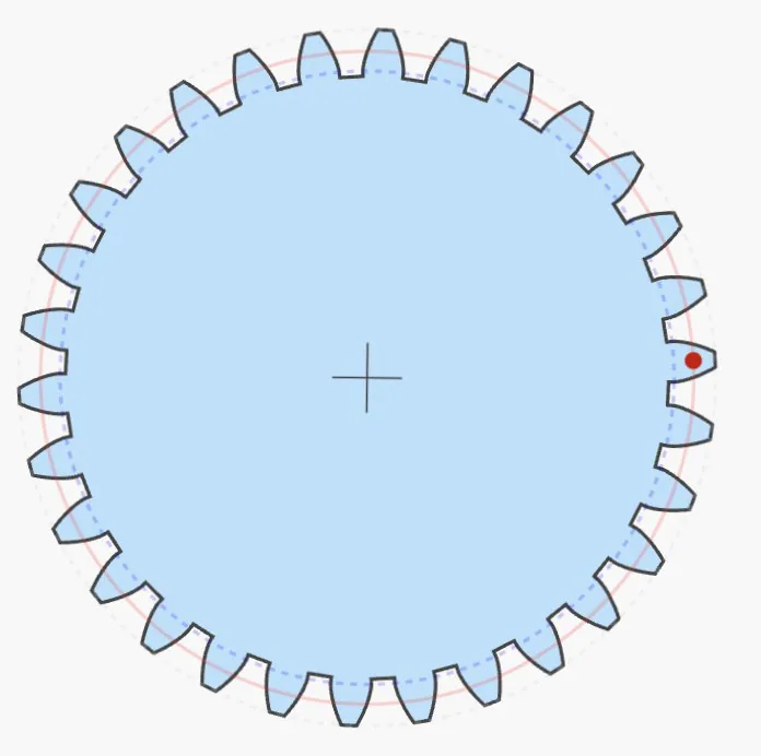
The module m = d/z, the ratio of the gear's pitch circle diameter (d) to its number of teeth (z).
The larger the module and the thicker the teeth, the greater the load a gear can carry.
Gears must have the same module to mesh properly. The module is expressed in millimeters (mm).
Example: for a 30-tooth gear with module 1, m = 1 = (30 mm / 30 teeth), so its diameter is 30 mm.
The plastic gears that are easy to buy online usually have a module of only 0.5 (m = 0.5). With the same number of teeth, the gear is smaller and cannot carry as much load.
Example: for a 30-tooth gear with module 0.5, m = 0.5 = (15 mm / 30 teeth), so its diameter is 15 mm.
A wind turbine's rotor experiences large torque as it spins, and the gearbox has to transmit that same large torque. For classroom wind turbine kits, we therefore recommend a gearbox module greater than 0.5. The larger the blade radius, the greater the torque, and the larger the module needs to be.
The MiniWind kit has a blade radius of only 15 cm, yet its gear set uses module 1. This lets it carry more torque, and if the gear set is assembled with small errors, the larger module tolerates some backlash so the gears still drive each other.
There are many kinds of gears. To keep things simple, they can be grouped into two broad categories: parallel-axis gears and intersecting-axis gears.
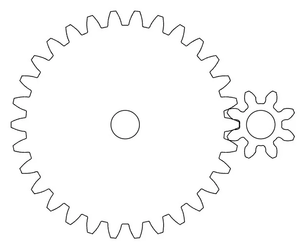
Parallel-axis gears include spur gears, racks, internal gears and helical gears.
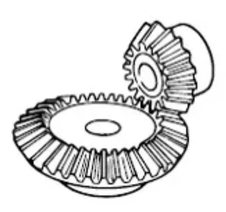
Intersecting-axis gears change the direction of the drive shaft, usually by 90 degrees. The most common types are bevel gears and worm drives.
A gear set can change rotational speed, change torque, or change the direction of transmission.
Let's design a gear set that increases rotational speed nine times, using the simplest case: spur gears.
If the large gear has 90 teeth and the small gear has 10, one turn of the large gear moves 90 teeth past the small gear, so the small gear must turn 9 times.
This does increase the speed nine times, but a 90-tooth gear is very large. On a wind turbine it would disturb the airflow and greatly reduce the efficiency of the blades.
Speed = large gear 90 teeth / small gear 10 teeth = 9 times
With a 30-tooth large gear and a 10-tooth small gear, the speed increases only 3 times.
Next, fix the 10-tooth small gear to a second 30-tooth large gear on the same shaft. Mesh that 30-tooth gear with another 10-tooth gear, and the speed increases another 3 times.
The total speed increase is 3 × 3 = 9 times.
Speed = (large gear 30 teeth / small gear 10 teeth) × (large gear 30 teeth / small gear 10 teeth) = 9 times
Option 2 saves a lot of space. Its drawback is that it needs three shafts instead of the two in Option 1, which adds friction at the shafts.
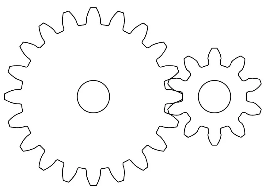
A higher gear ratio increases speed, but it reduces torque. The gear sets in the figure below have gear ratios of 2:1 and 3:1.
A weight W hangs from a thread wound around the large gear's shaft and descends a distance d; this represents the torque produced by the wind turbine rotor. Comparing the two gear sets shows clearly that the 2:1 set can use a thread to lift a load of less than W/2 a distance of 2d around the small gear's shaft, while the 3:1 set can lift a load of less than W/3 a distance of 3d.
The small gear lifting a load represents driving the generator to produce electrical energy. The 3:1 set lifts the load 3d, showing that a higher gear ratio produces faster rotation. But it can only lift a load of less than W/3, showing that the price of a high gear ratio is lower torque.
At the same wind speed, there are two ways to make the generator spin faster and produce a higher voltage: raise the rotor's tip speed ratio, or raise the gear set's gear ratio.
However, raising a rotor's tip speed ratio from 3 to 6 only doubles it, and it is very hard to push it any higher.
With a gear set, on the other hand, changing the gear ratio from 2:1 to 3:1, 4:1, 5:1 or 6:1 can easily more than double the speed; increasing it eight or nine times is no problem at all.
Adjusting the blade pitch angle, though, is simpler and more convenient. Changing the gear ratio means swapping in gears with different numbers of teeth and readjusting the gear spacing, which is far less convenient unless you have a shiftable gearbox like a car's.
Teacher insight: real commercial wind turbines use multi-speed gearboxes similar to a car transmission, which automatically switch gear ratios according to wind speed to keep the generator in its optimal speed range. This is why the gearbox of a large wind turbine is one of its most expensive and failure-prone components.
The driver gear sits on the blade side; the driven gear sits on the generator side.
Each turn of the blades spins the generator 3.00 times; torque drops to just 33%, so the blades need enough force to drive it.
Gear ratio = driver teeth ÷ driven teeth. As generator speed goes up, torque goes down by the same ratio (ignoring friction losses).
Related units: Elementary Unit 6; Junior High Unit 10; Senior High Unit 9
One question per stage: read it, choose an answer, then press Check answer.
Loading questions…
Related units: All units at all three levels