載入中…

Teaching Resources / Level 1 · Explore / Unit 12
Assessment: Scenario-based analogy questions in class (such as the analogy of carrying a passenger on a bicycle); a paper-and-pencil quiz on terms and formulas; formative assessment with a qualitative observation log of short-circuit and no-load spinning.
PPT (coming soon)
Background knowledge from Chapter 2 of this unit's Teacher's Guide. Use it with the interactive lessons below in class.
Before guiding students through this unit, teachers need a solid, cross-disciplinary grounding in basic electricity and electromagnetism. Because the flow of electrons and the electromagnetic conversion inside a generator are invisible, students' most common misconception is to treat wind power as a simple mechanical problem: "as long as it spins fast enough, the voltage will keep climbing and the power output will be unlimited." Teachers should be able to turn difficult physics (such as Lenz's Law and the maximum power transfer theorem) into easy everyday analogies, and clearly explain how electrical load, magnetic damping and electrical power interact. This makes it possible to give accurate, physically grounded explanations when students face all kinds of puzzling test data and setbacks.
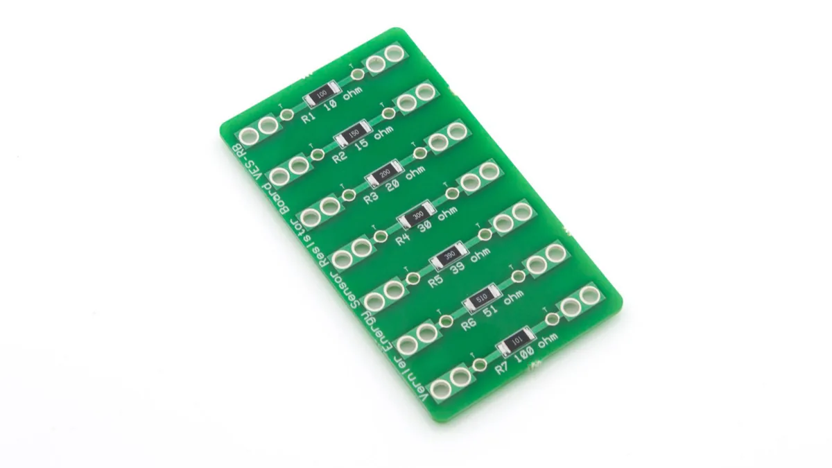
In electrical and wind engineering, a load is any device connected to a circuit that consumes electrical energy and converts it into another form of energy (such as light, heat or motion) to do work. The LED bulbs that light the classroom, a driver that turns a motor, and the Vernier Resistor Board used in the lab to turn electricity into heat are all loads.
To make this abstract idea concrete for elementary students, use the analogy of a bicycle carrying a passenger. When a wind turbine is turned by the wind without being connected to any external circuit (no load, open circuit), it is like riding a bicycle with a tailwind on a flat road: pedaling feels effortless and the wheels (the blades) spin quickly. But as soon as we connect the generator's wires to a bulb or a resistor board (adding a load), it is as if a heavy passenger suddenly sits on the back seat. That passenger takes energy from the rider to move forward. As electrons flow through the wires and the load, they meet resistance, and this resistance pushes back on the generator shaft as a physical reaction force, making the generator much harder to turn. The more devices connected and the more power they draw (that is, the lower the circuit's equivalent resistance and the larger the current), the heavier the passenger and the harder the rider has to pedal.
Before taking digital measurements, teachers must break the common misconception that high voltage means strong generating ability. In electrical engineering and wind energy assessment, measuring the voltage of a generator that is not connected to any load tells you nothing objective about how much energy the turbine actually extracts from the wind. The one true measure of turbine performance is power, not voltage or current alone.
The first key quantity is voltage (unit: V). Voltage can be pictured as the water pressure, or push, that drives electrons forward. Whenever the turbine's rotor spins in a magnetic field and cuts magnetic field lines, a voltage is produced. Even when spinning freely with no load, there is still a high voltage across the generator's terminals. The second quantity is current (unit: mA or A). It is the amount and rate of electrons actually flowing through the wire, like the flow of water in a pipe. If the circuit is not closed (no load), it is like a shut tap: no matter how high the pressure (voltage), the flow (current) is zero.
The third and most important quantity is power (unit: mW or W). It is the rate at which the generator actually does work, and it represents its real generating performance. The formula is: power = voltage × current. This formula reveals a hard truth: when the turbine spins with no load, the sensor may show an impressive 5 V, but because the circuit is open and the current is 0 mA, the product is P = 5 × 0 = 0 mW. The generator is delivering no useful energy at all. Only when a load is connected and current can flow is mechanical energy actually converted into electrical energy and delivered.
When students connect the turbine to a very low resistance (a very heavy load), or even touch the red and black wires together to short-circuit it, they are surprised to see a turbine that was racing in a strong wind suddenly slow dramatically, sometimes groaning almost to a stop. This contradicts their intuition that the same wind should give the same speed, and the explanation lies in Lenz's Law.
Lenz's Law is one of the core laws of electromagnetism. It states that when a coil of wire moves in a magnetic field and an induced current is produced, that current creates a new magnetic field of its own, and the direction of this new field always opposes the motion that produced it. It can be thought of as the electromagnetic counterpart of Newton's third law (action and reaction), and it follows necessarily from the law of conservation of energy.
In everyday language: inside the KidWind generator are coils of copper wire and strong magnets. When the wind pushes the blades and forces the copper wire to spin past the magnets, a flow of electrons (a current) is pushed through the wire. But this current is stubborn: the magnetic force it creates acts like two magnets with like poles facing each other, pushing hard against the spinning blades and trying to brake them. In wind engineering we call this invisible braking force magnetic damping.
The smaller the load resistance students connect (for example 10 Ω, or 0 Ω for a short circuit), the larger the current in the circuit. The larger the current, the stronger the magnetic field from Lenz's Law, and the stronger the magnetic damping (the braking force). This large electromagnetic braking force overwhelms the mechanical force of the wind on the blades, so the turbine slows sharply. Once it slows, the generator cuts magnetic field lines much more slowly, so the push (voltage) also drops sharply. That is the underlying reason why, in very low-resistance tests, the current looks large but the voltage falls so far that the total power calculated with P=IV ends up very low.
Magnetic damping leads to an advanced engineering question: if the external resistance is too high, the current is too small and power is low; if it is too low, magnetic damping slows the rotor, the voltage collapses and power is also low. So what load should the generator be connected to?
In circuit theory and electronics, the answer is known as the Maximum Power Transfer Theorem. It states that when the external load resistance exactly equals the internal resistance of the generator (the source), also called its Thévenin equivalent resistance, the power delivered to the load reaches its maximum.
This is the scientific purpose behind having students test resistances of 100 Ω, 51 Ω, 30 Ω and 10 Ω in turn. The small DC motor used as the generator in the basic KidWind turbine has some internal resistance in its coils and brushes. When students plot their data as a line graph, they will find the curve is not a straight line but an inverted U. The external resistance at the top of the curve, which gives the highest power (mW), is the turbine system's optimal load at that wind speed. It represents the best physical compromise between the mechanical energy input from the wind, the generator's electromagnetic conversion efficiency and the load's ability to consume energy.
Small-scale lab investigations should connect closely to real-world sustainability challenges. Guide students to think like engineers: in the classroom, the fan blows at a fixed wind speed, so we can find a single optimal load (for example 30 Ω). But in nature, monsoon winds and ocean air currents rise and fall, full of turbulence and gusts. This means the turbine's mechanical energy and generating capacity change every second, and its ideal matching point drifts along with them. If we wired a fixed resistive load to a turbine at sea, it would spend most of its time away from its optimal operating point, wasting a great deal of clean energy.
To solve this, the control systems of modern offshore wind farms and solar power plants use an advanced digital algorithm called Maximum Power Point Tracking (MPPT). An MPPT system acts like a very smart digital brain for the turbine. It measures the generator's output voltage and current thousands of times per second and, through power electronics such as converters, continuously adjusts the equivalent load connected to the generator. When a strong gust arrives and the system gains energy, it instantly increases the load (lowering the equivalent resistance) to draw more current from the generator; when the wind suddenly drops, it immediately lightens the load so magnetic damping does not brake the turbine to a stop. With MPPT and smart grid technology, engineers make sure we capture as much clean electricity as possible from every gust, in line with SDG 7 and SDG 9.
With no load (open circuit) it’s like riding a bike alone: pedalling is easy and the blades spin fast, but there’s no current, so no electricity.
Mission: try all six loads. Start with “Open circuit” – like riding a bike with no passenger – then switch to 100, 51, 30 and 10 Ω and “Short circuit”, and watch how the blade speed and power change.
Related units: Elementary Unit 12; Junior High Unit 12; Senior High Units 7, 9, 10
Open circuit: no current means no magnetic braking, so the blades spin fast and the voltage is highest (4.49 V). But P = V × 0 = 0 – no energy is delivered.
Open circuit: no current means no magnetic braking, so the blades spin fast and the voltage is highest (4.49 V). But P = V × 0 = 0 – no energy is delivered.
Six-load challenge Tried 0 of 6
Make a guess: which resistance produces the most power? Start with “Open circuit”.
One question per stage: read it, choose an answer, then press Check answer.
Loading questions…
Related units: All units at all three levels